The Physical network diagram
The Physical network diagram (IE. the floor plan) is built to scale. Each of the wire runs is calculated, plus 10% more for maintenance and going up and down walls and a “service loop” so that the wires can easily come out of the walls for maintenance.
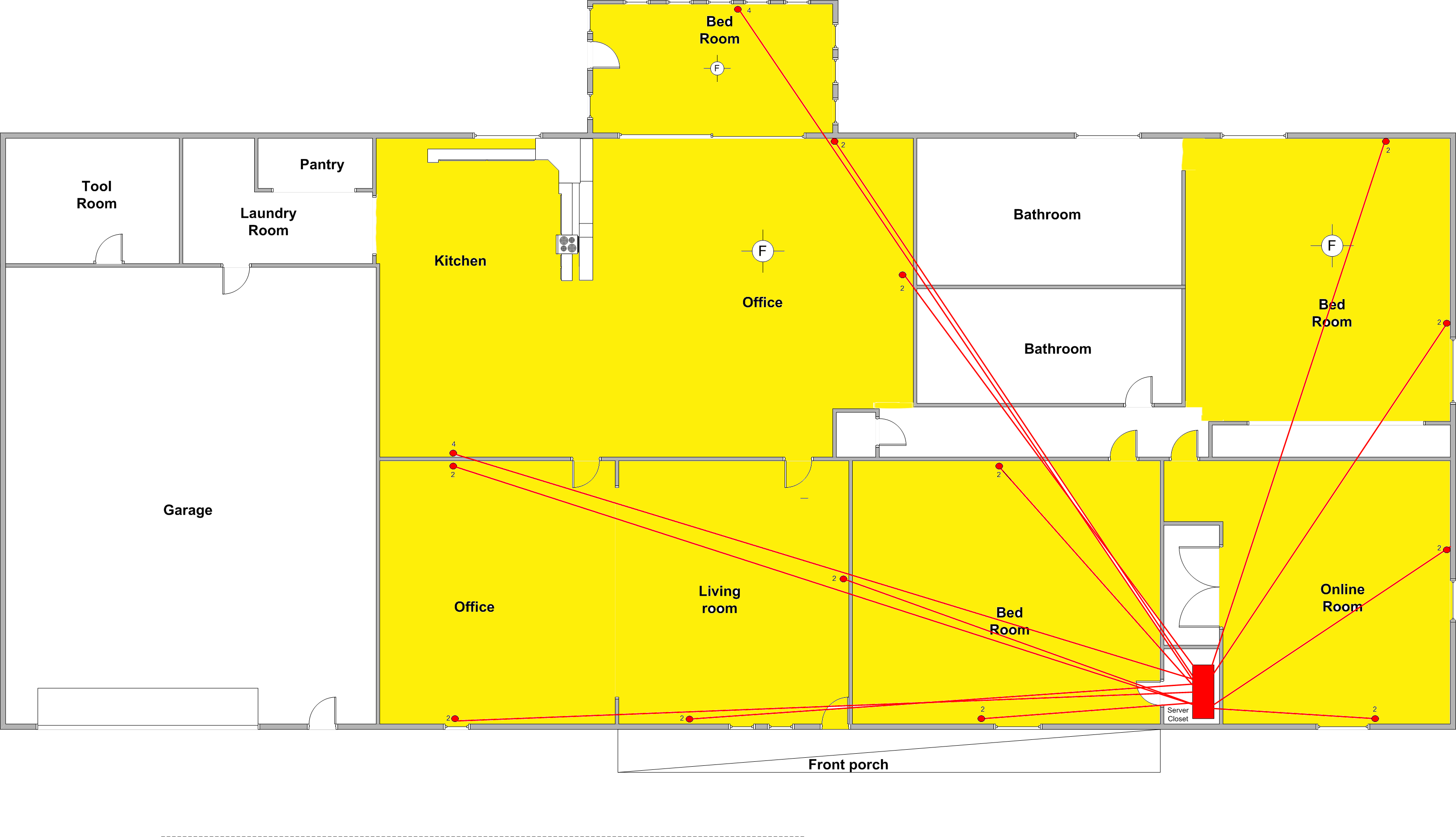
I used a program called Visio from Microsoft to do the measurements and my diagram. You can also use graph paper and measure each of the wire runs.
Home Ethernet wiring
- t will take 32 runs of CAT 6 wire to wire all of the essential rooms. Approximately 2 rolls of CAT 6 plenum wire. (Cable color code: blue)
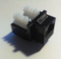
- Two 4-outlet plates and twenty-four 2-outlet plates
- Thirty-two terminator blocks for the wires to the plates
- A forty-eight punch-down – I may want to expand the network and put in a few IP cameras.
- A four way 110 volt grounded outlet and a 110 volt grounded outlet for the power strip.
- Lighting for the closet
- AC run off of one of the main lines into the closet
- 32 3-foot cables to go from the punch down panels to the switch (Cable color code: Red)
- 2 3-foot wires to go from the security appliance and the router to the switch (Cable color code: green)
- 2 8-foot wires to go from the NAS and server to the switch (Cable color code: green)
- All of the wires labeled
- All outlet wires labeled (inside of the wall plates)
- Every wall plates labeled
|
Tools Needed:
- Phillips Screwdriver
- Punch down tool
- Wire cutters
- Drill (Optional)
- Glow Rods or fishing tape reel
- Zip ties
|
You can find most of the cabling and the punch down panels that I mentioned at cables2go.com. I endorse them even though I don’t get any monetary benefit from it. I have used them extensively an like their services and products.
My APC Power bar and APC UPS, which I already have (from other jobs), will go into the rack. I will need at least a 2 1U shelves to house the security appliance, router, server and NAS.